Modern service tools and onboard control units now shape how owners and shops spot faults and tune performance.
Volvo cars use dealer-grade platforms like VIDA and PTT, paired with hardware interfaces, to pull sensor data and run targeted checks.
These systems link the 12V electrical network and the high-voltage propulsion pack to central control modules.
That path—from sensors to control units to service tools—turns raw readings into clear repair steps.
Accurate diagnostics matter for safety, range, and long-term reliability as more functions migrate into centralized software.
This guide is for independent technicians, fleet managers, and enthusiasts in the United States who want a practical workflow and a clearer view of the service-tool stack.
Key Takeaways
- Dealer-grade platforms like VIDA/PTT are central to modern diagnostics.
- Interfaces such as Volvo VCI and J2534 let techs read faults and run tests.
- Diagnostics cover both 12V electrical systems and high-voltage propulsion packs.
- Software-defined controls improve safety and long-term performance.
- This guide helps U.S. techs and owners map tools, codes, and repair actions.
What “battery diagnostics” means in modern Volvo vehicles
Ongoing monitoring and on-demand tests evaluate charge level, voltage trends, temperature behavior, and fault events across the car’s energy systems. This process combines live telemetry with targeted checks to turn raw readings into clear service actions.

How diagnostic data supports safety, reliability, and long-term performance
Safety improves because stored events and live signals expose hidden faults that visual inspection can miss after an impact. Technicians see history, not just a single snapshot, which aids in ensuring safety.
Reliability rises when early detection prevents repeat failures. Alerts for abnormal voltage drops or temperature excursions stop unexpected no-starts.
Performance depends on stable voltage under load and correct charge behavior. Healthy charging and consistent cell behavior keep drivability and range steady over time.
The difference between 12V electrical system diagnostics and high-voltage monitoring
12V checks focus on power distribution, parasitic draw, wake/sleep behavior, and DC-DC or alternator charging paths. High-voltage monitoring inspects cell-level voltages, isolation status, and thermal management inputs.
| Scope | Data Points | Service Outcome |
|---|---|---|
| 12V electrical system | Voltage under load, parasitic draw, charging rates | Restore start reliability, fix accessory power faults |
| High-voltage pack | Cell voltages, temperatures, isolation resistances | Protect range, prevent thermal events, confirm pack health |
| Networked diagnostics | Stored DTCs, freeze-frame, live parameters | Contextual repair steps and confirmation over time |
How does Volvo integrate battery diagnostics into vehicle software?
Central controllers collect sensor inputs and decide when a reading should become a recorded fault. Physical sensors feed control modules on the car’s networks. The Battery Energy Control Module (BECM) aggregates cell and pack signals and runs the live management logic.
Readability for techs comes from converting raw values into thresholds, plausibility checks, and timed rules. When rules trigger, the BECM sets DTCs and exposes readable parameters for service tools.
The flow to external tools uses standard communication paths. VIDA/PTT and a compatible interface request live streams and stored events so technicians get consistent information access across shops.
Monitoring is designed to run continuously without impacting normal drivability. Logging uses minimal compute, prioritizes safety functions, and balances false positives by tuning criteria to real-world use and aging.

Quick comparison of roles in the stack
| Layer | Role | Service output |
|---|---|---|
| Physical sensors | Measure voltage, temp, isolation | Raw inputs for evaluation |
| Control modules (BECM) | Aggregate, evaluate, set DTCs | Stored faults and live parameters |
| Service tools & interfaces | Read streams, run tests, log results | Technician access and repair steps |
The onboard hardware and components that generate battery health insights
A network of dedicated control modules and sensors produces the raw data used to assess pack health.
Diagnostics are outputs of modules that interpret inputs from physical equipment, not the pack casing itself.
Battery Energy Control Module and internal control modules
The Battery Energy Control Module (BECM) owns high-voltage evaluation. It aggregates voltages, temps, and isolation values.
BECM sets fault codes, exposes live parameters, and coordinates with internal control units for safe operation.
Cell voltage and temperature units
Cell Voltage and Temperature Nodes (CVTN) sample at cell-group level. These sensors enable balancing and thermal protection.
Accurate sensor readings let the control modules detect drift, overheating, and failing cells before they cause bigger faults.
Battery Disconnecting Unit and Manual Service Disconnector
The Battery Disconnecting Unit (BDU) uses contactors and fuses to route high-voltage power safely.
The Manual Service Disconnector (MSD) is a physical safety stop for service. Software reports the MSD state so technicians see the changed safety configuration.
Mild-hybrid charge control path
For mild-hybrid systems the Central Electronic Module (CEM) manages charge flow. The Integrated Starter Generator Module (ISGM) charges the 48V pack.
The Mid-Voltage Converter Module (MVCM) then supplies 12V charging for the main battery, so faults in that path can cause slow charging or no-crank symptoms.
| Hardware | Role | Common symptom |
|---|---|---|
| BECM | Aggregate data, set faults | Stored DTCs, charge inhibit |
| CVTN / sensors | Measure cell volt/temp | Imbalance, thermal warnings |
| BDU / MSD | HV routing and service safety | No-start, isolation faults |
| CEM → ISGM → MVCM | Mild-hybrid charge path | Slow 12V charge, reduced assist |
Volvo’s software and service tools that connect vehicle data to diagnostics
Technicians rely on a small set of purpose-built platforms and interfaces to turn sensor data into clear repair steps.
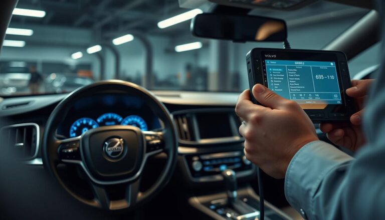
VIDA for Volvo cars: vehicle information, guided repair, and software downloads
VIDA is the central workflow hub for Volvo cars. Techs read fault codes, view live parameters, follow guided diagnostics, and perform targeted software downloads when needed.
This tool gives VIN-based information and step-by-step procedures that reduce guesswork during testing and repair.
PTT for trucks, buses, and heavy equipment: full-system diagnostics and ECU programming
PTT covers full-system diagnostics for commercial platforms. It supports fault tracing, ECU programming, calibration, and parameter setting in a controlled service flow.
For heavy equipment, PTT provides the deeper access required for complex ECU work and system-level testing.
EWD and Impact for electrical troubleshooting and repair planning
EWD supplies detailed wiring diagrams so technicians can trace circuits, grounds, and connectors rather than guess which branch causes a fault.
Impact complements EWD with repair manuals, service bulletins, maintenance schedules, and a parts catalog tied to VIN lookup. This reduces incorrect parts orders and rework.
What a VCI or J2534 pass-thru interface does during testing and updates
A Volvo VCI or a compatible J2534 pass-thru is the physical bridge between the vehicle network and a Windows PC.
It provides protocol translation and secure access so VIDA or PTT can stream live data, run active tests, and apply module updates during a shop session.
| Tool / Interface | Main Function | Service impact |
|---|---|---|
| VIDA | VIN lookup, guided diagnostics, software downloads | Faster fault isolation; fewer repeat repairs |
| PTT | Full-system diagnostics, ECU programming/calibration | Comprehensive commercial vehicle testing and updates |
| EWD | Wiring diagrams and electrical troubleshooting | Quicker isolation of circuit and connector faults |
| Impact | Repair procedures, service bulletins, parts catalog | Improved repair planning and correct parts ordering |
| VCI / J2534 | Physical link for testing and module updates | Enables live data access and secure software flashes |
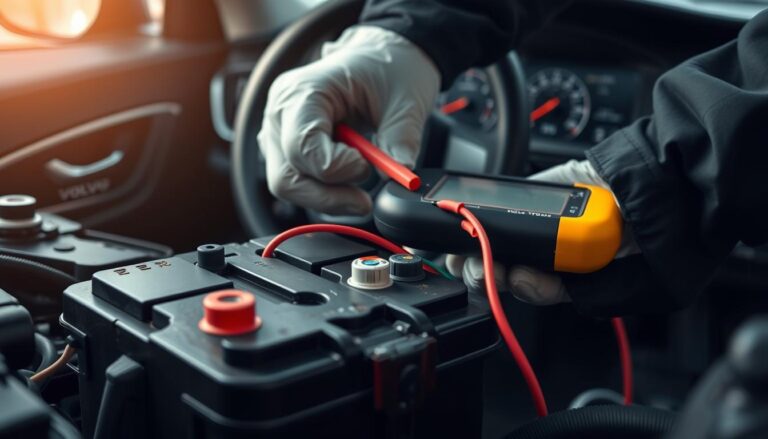
A practical workflow to run battery diagnostics on Volvo systems
Start every service session by securing stable 12V power. Connect a battery maintainer before opening VIDA or running long data captures. This prevents module resets and avoids false faults during software downloads.
Prepare and stabilize power
Attach the maintainer to the 12V terminals and confirm proper clamps and polarity. Leave the maintainer connected for the full session when VIDA will stream live parameters or flash modules.
Connect tools and collect data
Hook up the VCI, identify the vehicle in VIDA, and pull stored codes. Capture live parameters and a controlled data log so you have baseline readings before any intervention.
Trace faults with wiring and repair info
Use EWD to follow power and ground paths. Cross-check pinouts and expected voltages in Impact or VIDA task guides. That lets you narrow issues across parts, converters, wiring, and control modules.
Validate fixes and finalize
After replacement or repair, rerun scans and perform active tests. Complete required calibrations and apply any indicated updates so the fix holds over time.
Document results
Save before/after logs, recorded parameters, and service steps in the job file. Clear records support warranty claims and protect residual value for the vehicle.
Safety and compliance built into Volvo’s diagnostic and repair process
Pre- and post-repair scanning is mandatory to reduce hidden risk and protect occupants, equipment, and technicians. A required scan uncovers silent faults in control modules, wiring, and sensors that warning lights may not show.
Why pre-repair scans matter
Volvo requires a scan before any work to verify current faults and module states. This step helps teams plan safe service steps and avoid introducing new risks when disconnecting parts or replacing components.
Post-repair verification
After repair, a second scan confirms that safety and driver-assist systems function correctly. Post-repair checks also identify required calibrations or initialization events caused by replacement or repair work.
Common repair triggers for scans
- Disconnected or replaced batteries and control units
- Wiring harness repairs and light or sensor replacement
- Body work affecting mirrors, cameras, windshields, or bumpers
High-voltage and post-collision rules
Only authorized Volvo workshops and certified technicians may handle high-voltage parts. HV replacement and major pack service must occur in authorized facilities to limit injury and technical risk.
After a collision, teams must not switch on ignition until inspected. If repairs are delayed, move the vehicle outdoors to a fire-protected area, cordon off the space, and assume the HV system is energized until verified. Inspect enclosures for leaks, deformation, arc marks, or damaged connectors before any hands-on work.
VIDA procedures dictate what may be touched and when. Documenting pre- and post-scan results protects liability and supports safe return-to-road decisions.
How adaptive charging software shows the next step in Volvo battery management
A new layer of charging logic actively tunes current and timing to match real-time cell conditions.
Volvo Cars integrates Breathe Charge into its in-house management platform to move charging from fixed profiles to live, model-based control.
Embedding model-based control into the management platform
The control system runs a physics-based model that estimates internal electrochemical states.
That model lets the platform adjust current and limits dynamically rather than follow lookup tables.
Faster 10–80% fills while protecting long-term health
Validation shows up to ~30% faster charge time from 10–80%. Real-world reports cite the ES90 reaching about 22 minutes for that window.
The adaptive approach increases driver convenience at public chargers while using safeguards to avoid lithium plating and preserve capacity over years.
Why real-time physics-based models beat static profiles
Physics-based models react to present temperature, state of charge, and aging. They tune current to push speed without crossing chemistry limits.
This yields better short-term performance and improved long-term reliability compared with stepped strategies.
“Adaptive charging is the new standard,” said Ann-Sofie Ekberg, with supporting commentary from Dr Björn Fridholm on longevity benefits.
| Feature | Benefit | Risk mitigated |
|---|---|---|
| Real-time physics model | Faster, tailored charging | Reduces lithium plating risk |
| Adaptive current control | Better 10–80% time performance | Avoids thermal spikes |
| In-house + partner approach | Faster deployment, vetted tech | Supply and integration risk lowered |
The partnership, with a Tech Fund investment and sourcing agreement, signals that battery charging technology is now a competitive investment area for the brand.
For related service planning and software upgrade costs, shops should consider trained workflows and tool support when enabling adaptive charge features.
Conclusion
This final summary ties the sensing, control logic, and shop workflows into one practical checklist for service teams.
On modern volvo cars the BECM and cell sensors feed live and stored data that service tools expose as DTCs and readable parameters. Effective repair is a system task: hardware supplies signals, logic interprets them, and tools guide tests and fixes.
Follow a simple workflow: stabilize 12V supply, run pre-scan and live capture, use wiring references to isolate faults, validate repairs with tests and updates, and save records.
Adhere to VIDA safety steps for high-voltage work. Looking forward, adaptive charging in the management software shows how smart control can boost charge speed while protecting long-term battery health. Consistent process and approved interfaces cut comebacks and raise performance.
FAQ
What does “battery diagnostics” mean in modern Volvo vehicles?
Battery diagnostics refers to the software and hardware functions that monitor cell voltages, temperatures, state of charge, state of health, and related electrical system parameters. These routines collect sensor data, calculate key metrics, detect faults, and log events so technicians and onboard systems can act on issues before they lead to failure or safety risks.
How do diagnostic data support safety, reliability, and long-term performance?
Diagnostic data reveal trends and early fault indicators that let control systems limit stress, adapt charging, and notify drivers or service centers. Early detection prevents cascading failures, preserves range and capacity, and supports warranty and lifecycle management. Reliable diagnostics also guide repairs and software updates that restore intended performance.
What is the difference between 12V electrical system diagnostics and high-voltage battery monitoring?
The 12V system uses dedicated controllers and simpler health checks for accessories, starters, and sensors. High-voltage battery monitoring involves cell-level sensing, battery management modules, isolation monitoring, and thermal supervision. HV diagnostics include more complex algorithms and safety interlocks due to shock and fire risks.
Where do diagnostics live in the vehicle software stack: control modules, networks, and the battery management system?
Diagnostics are distributed across control modules such as the Battery Energy Control Module (BECM), Battery Management System (BMS), Central Electronic Module (CEM), and propulsion ECUs. These units share data over in-vehicle networks (CAN/FlexRay/automotive Ethernet). A combination of local controllers and central gateways aggregates parameters and stores fault records for service access.
How are DTCs and readable parameters created and surfaced to technicians?
Manufacturers define diagnostic trouble codes (DTCs) and parameter IDs for monitored faults and live data points. ECUs set DTCs when thresholds or self-tests fail. Tools like VIDA present codes, freeze frames, and live values. Technicians use DTC definitions, troubleshooting trees, and guided procedures to interpret and act on the information.
How does Volvo design diagnostics to work without impacting normal vehicle functions?
Diagnostic routines run with defined priorities and timing constraints so they do not block real-time control tasks. Noncritical diagnostics are scheduled during idle periods or low load. Watchdogs and safety supervisors prevent diagnostics from interfering with traction, braking, or steering. The goal is fault detection with minimal performance overhead.
Which onboard hardware and components generate battery health insights?
Key hardware includes the Battery Energy Control Module, the Battery Management System with cell monitoring units, temperature sensors, current sensors, the Battery Disconnecting Unit (BDU), and manual service disconnectors. These devices measure voltages, currents, temperatures, and isolation resistance to build a complete health picture.
What roles do cell voltage and temperature sensors play?
Cell voltage and temperature sensors measure per-cell conditions to detect imbalance, overheating, and early degradation. Accurate sensing enables cell balancing, thermal management, and safe charge/discharge limits. Without these inputs, the system cannot protect cells or estimate remaining useful life reliably.
What is the function of the Battery Disconnecting Unit and Manual Service Disconnector?
The Battery Disconnecting Unit isolates high-voltage circuits during faults or when the vehicle is powered down. The Manual Service Disconnector provides a safe method for technicians to physically disconnect HV battery modules for repair or salvage. Both are critical for safety and regulatory compliance during service.
How are mild hybrid charge control and the 48V system managed?
Mild hybrid systems use controllers like the Central Electronic Module, Integrated Starter Generator Module, and dedicated charge control modules to manage 48V battery charging and energy recuperation. Diagnostics monitor the 48V battery, converters, and related wiring to ensure proper charge flow and prevent electrical faults.
What Volvo software and service tools connect vehicle data to diagnostics?
VIDA is Volvo Cars’ primary workshop tool for vehicle information, diagnostics, guided repair, and software downloads. For heavy vehicles, PTT offers full-system diagnostics and ECU programming. Electronic Wiring Diagrams (EWD) and Impact provide detailed electrical schematics and repair procedures. VCIs or J2534 pass-thru interfaces bridge the vehicle to these tools for testing and updates.
What does a VCI or J2534 pass-thru interface do during testing and updates?
A Vehicle Communication Interface provides a secure data link between the vehicle network and diagnostic software running on a laptop or cloud service. It allows reading DTCs, streaming live data, performing active tests, and flashing ECU software via standardized protocols such as J2534.
What is a practical workflow to run battery diagnostics on Volvo systems?
Begin by stabilizing vehicle voltage with a battery maintainer and confirming the vehicle identity in VIDA. Connect the VCI, retrieve stored codes, and record live parameters. Use wiring diagrams to isolate faults, perform active tests and calibrations, and apply any required software updates. Finally, validate the repair with post-repair scans and document results for service history.
Why prepare the vehicle and stabilize voltage during VIDA sessions?
Stable voltage prevents spurious DTCs and ensures ECUs remain powered during data exchanges and flashing. A battery maintainer or charger avoids unexpected shutdowns that could corrupt module software or calibration data.
When should wiring diagrams and repair information be used to isolate faults?
Use wiring diagrams after retrieving codes and live data to trace signal paths, connector locations, and splice points. Accurate diagrams speed root-cause analysis for sensors, harnesses, and control modules and reduce unnecessary parts replacement.
How are repairs validated with active tests, calibrations, and software updates?
Active tests command actuators or simulate signals to confirm component behavior. Calibrations align sensors and controllers after replacements. Software updates restore known-good logic or address firmware bugs. Together these steps confirm the system meets design performance and safety requirements.
Why document diagnostic results for service history, warranty, and residual value?
Detailed records support warranty claims, prove proper maintenance, and preserve resale value. Service history shows that diagnostics and corrective actions followed manufacturer procedures, which insurers and future buyers often require.
Why does Volvo require pre-repair scanning even when no warning lights appear?
Pre-repair scans catch latent faults, pending DTCs, or logged events that a single lamp may not reveal. This prevents missed issues, avoids incomplete repairs, and ensures safety systems and automated functions remain intact after service.
What is the role of post-repair scanning?
Post-repair scans verify that DTCs cleared, calibrations completed, and autonomous or driver-assistance systems function correctly. They confirm the repair resolved the root cause and that no new faults resulted from the work.
Which repair events commonly trigger scans?
Battery replacements, control unit swaps, wiring harness repairs, headlamp or sensor work, and collision repairs typically require scanning. Any event that can affect monitored circuits or control units should include diagnostic checks.
What are the rules for high-voltage handling and authorized workshops?
High-voltage systems must be serviced only by certified technicians using prescribed PPE, tooling, and isolation procedures. Volvo mandates authorized workshops for HV repairs to meet safety, legal, and warranty obligations.
What post-collision precautions apply to EV batteries?
After a collision, technicians must inspect for thermal damage, mechanical deformation, coolant leaks, and compromised isolation. Procedures include battery isolation, detailed inspection points, and fire-risk mitigation steps before recovery or repair.
What is adaptive charging software and why does it matter?
Adaptive charging uses model-based control and real-time cell measurements to tailor current, voltage, and thermal limits during charge. This approach shortens charge time while protecting cell chemistry and extending battery life compared with fixed lookup-table strategies.
How does model-based control improve charging from 10 to 80%?
Physics-based models predict cell response and adjust charge power to maximize speed while avoiding overheating or accelerated aging. This dynamic control can reduce charge time without sacrificing long-term health, improving user experience and range recovery.
Why do real-time physics-based models outperform traditional lookup-table charging strategies?
Real-time models account for current state-of-charge, temperature, cell imbalance, and degradation to make informed trade-offs. Lookup tables use conservative estimates and cannot adapt to individual pack conditions, so models deliver safer, faster, and more efficient charging per vehicle.